Digital multi-meter
When measuring the resistance of something is a great deal more complicated if that resistance is very small. With bigger resistances, measurements can be as simple as connecting two leads between a digital multi-meter (DMM) and the device under test (DUT) and reading the number. With small resistances, the multitude of physical effects that are negligible at bigger values can no longer be neglected, and focus shifts to minimizing them, or compensating for them, as far as possible.
A prime examples the resistance of the leads connecting the test instrument to the DUT. When you consider that the leads might be adding 10mΩ to 1Ω, this is certainly significant if the resistance you’re trying to measure is under 100Ω. In this case, the Kelvin (four-wire) method should be used, which measures the current and voltage through separate pairs of leads (see Figure 1). The current is supplied through a low impedance, highly accurate, current source that will auto-compensate for the current lead resistance. The voltage is measured with a high impedance circuit, typically 1 MΩ. Adding the voltage lead resistance to this high impedance is insignificant. All precision test instruments should support this four-wire setup.

Click image to enlarge
Figure 1: The Kelvin method of measuring resistance
When resistances are below 100mΩ, higher currents than are typically available in standard bench DMMs are required. A typical bench DMM will only be able to source around 10mA. On a 10mΩ resistor, this is only a 0.1mV signal. Even 7.5 or 8.5 digit DMM will be unable to accurately measure these resistances. A special purpose micro-Ohmmeter will be required that can source at least 1A.
Accurately measuring resistances below 1mΩ
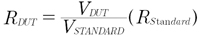
When accurately measuring resistances below 1mΩ typical of high current shunts will require a more elaborate setup (see Figure2). In this case a ratio measurement is employed using a precision standard of known resistance hooked up in series with the DUT and a current source. Since the current is the same through both resistors, the resistance of the DUT can be directly calculated with the following formula:
Click image to enlarge
Figure 2: The Ratio method of measuring resistance
The current needs to be high enough to produce a good voltage signal and it must be stable, >5mV is usually sufficient with good DMMs. The standard resistor should be within an order of magnitude of the DUT. Example, a 1mΩ standard can measure an unknown resistance between 0.1mΩ and 10mΩ.
Handling heat
Thermal effects are another source of error that become non-negligible at low resistances. The thermocouple effect, which generates a small thermal EMF anywhere two dissimilar metals are connected, appears at the connections between the leads, DUT and instrument. Using all copper connections can help, as well as using an instrument with some kind of built-in compensation.
There are several widely-used schemes: offset compensation measures the voltage at zero current to find the thermal EMF and subtract it, while current reversal compensation takes readings at opposite current polarities, and averages the results. However, for both of these schemes, the instrument needs to perform the two readings in very fast succession. If the temperature is fluctuating such that it’s not possible to get a consistent reading, there’s a third method called the Delta method, which applies the current reversal method several times in quick succession and estimates the voltage drift so it can be compensated for.
Selecting the right test current
Selecting the right test current can also have an effect on accuracy. While bigger test currents are usually seen as favorable (as they increase measurement resolution), go too big and the resulting power dissipation in the DUT will result in self-heating, which will not only affect its resistance but also increase the thermocouple effect. Some instruments offer a current pulse mode to minimize self-heating, while others offer a selection of test currents or simply a ‘low-power’ mode.
The test voltage is also important. In very low-voltage circuits, the voltage across the contacts may not be entirely linearly proportional to the current through it, due to oxide films on the metal contact’s surface. Changing the measurement range on the instrument is a good way to tell whether this effect is in play – the readings will be different resolutions but should still be consistent. To counter non-ohmic contact resistance, combine indium or gold contacts with increased test voltage and use offset compensation.
The good news is that modern precision test equipment can compensate for a lot of these effects which can otherwise result in inaccurate readings. However, a thorough understanding of the appropriate measurement techniques is still essential.