
In any system where heat dissipation could affect the components’ performance, understanding power dissipation for the purposes of selecting the right heat sink is very important. Let’s take a closer look at the power dissipation of resistors.
Standard Conditions for Specifications
The first thing to understand is the manufacturer’s specification for the resistor in question. In Riedon data sheets, the nominal power dissipation is mentioned for all resistors. The data is valid for a free standing assembly, that is, an SMD assembled on a PCB. The ambient temperature is always 70°C. This means that the inherent temperature of the resistance element (the sum of the ambient temperature and the temperature through the power dissipation) will reach the limiting temperature if additional cooling is not used.
Derating
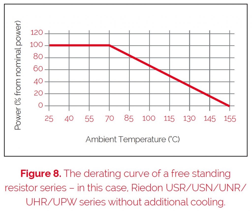
If the ambient temperature is higher than 70°C, the power dissipation must be reduced to secure that the resistance element will not exceed the limiting temperature. Otherwise the element will be damaged.
This necessary reduction of the power dissipation is called derating. A derating curve should always be shown in the resistor’s data sheets (see figure 8).
The value of the specific power dissipation depends on the ambient temperature, usually given as a percentage of the nominal power dissipation. If the ambient temperature reaches the limiting temperature of the element, it is not possible to electrically stress the element. If the ambient temperature is below 70°C, it is possible to stress the element with a higher power than mentioned in the data.
Cooling Techniques
The power dissipation can be increased even further if an additional cooling system is used (ie, a heat sink or forced air cooling).
The most effective method is forced air cooling with a ventilating fan. With this additional cooling, the heat convection of the resistor can be higher. In general, with forced air cooling of 3 m/s and optimal placement of the fan, it is possible to double the resistors’ power dissipation.
Another possibility is the use of a heat sink. A heat sink effectively increases the surface area of the resistor, resulting in higher convection. All Riedon resistor series use packaging designed to have a heat sink mounted on it (for example, TO 220 and TO 218).
The resistors’ data sheets show the nominal power dissipation when the resistor is used with a heat sink. The specifications are valid under the following conditions:
- Assembled on a heat sink with optimal fixed mounting (pressurized and with the use of a heat conduction paste)
- Temperature of the heat sink is 25°C (for power resistors, 40°C)
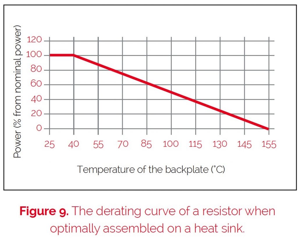
With the resistor is installed on a heat sink, the derating curve looks different from the freestanding assembly. The power dissipation depends on the temperature of the case bottom plate (figure 9).
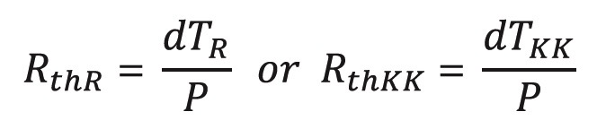
To calculate the thermal resistance of the resistor or the heat sink (note that the thermal resistance of the heat sink must be obtained from the manufacturer of the heat sink):
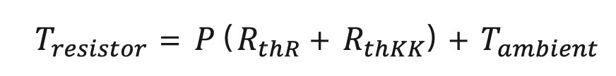
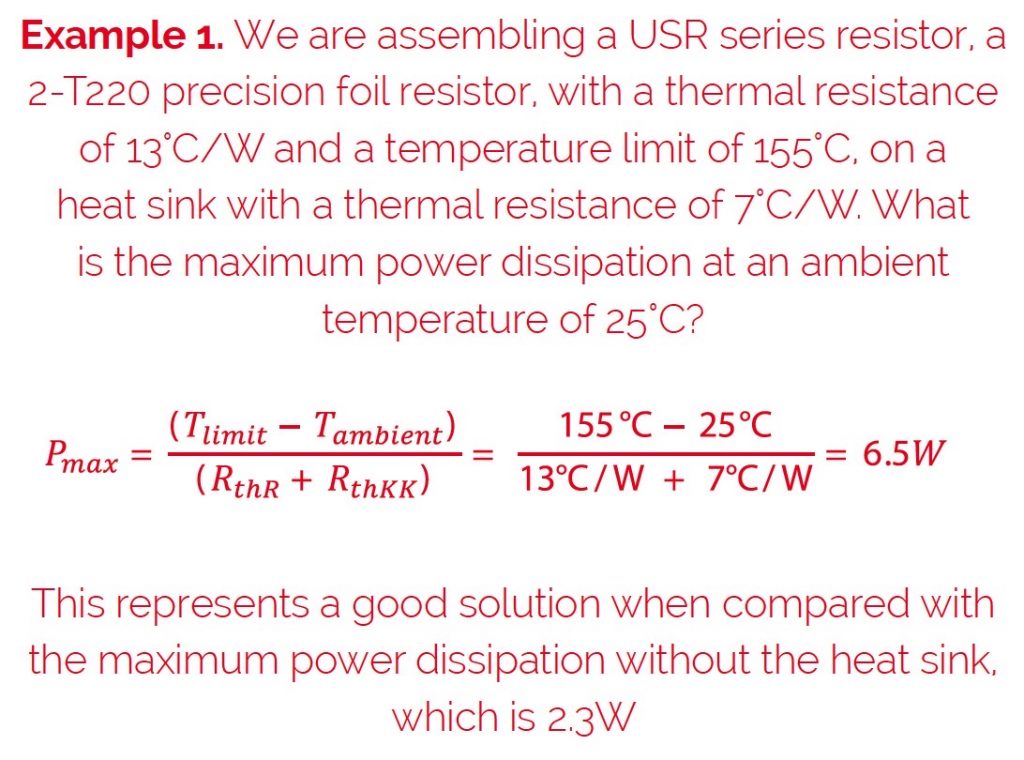
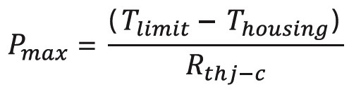
In order to calculate the maximum power we have to use the following equation which results from the former equations:
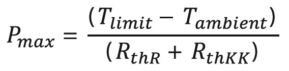
The maximum allowed power dissipation depends on the temperature of the heat sink, because the inherent temperature is the sum of the heat from the power dissipation and the heat sink temperature itself.
For the maximum allowed power dissipation, the following condition is valid:
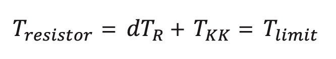
Where Tresistor is the inherent temperature of the resistor, dTR is the increase in temperature caused by the resistor power dissipation, TKK is the heat sink temperature, and Tlimit is the limiting temperature.
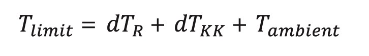
When the resistor gets hot, it heats up the heat sink. The temperature of the heat sink rises above the ambient temperature of the application, Tambient. TKK is now Tambient plus the change in TKK, dTKK.
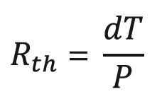
Thermal resistance is the factor of proportionality between the power dissipation, P, and the increase in temperature. We can calculate this as follows:
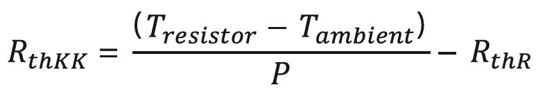
 Another use case for heat sink mounted resistors is to reduce the change in temperature in order to reduce the associated change in resistance, to increase the stability for precision applications. In this case, the inherent temperature will be constant at the same power dissipation. In order to calculate it, we need the following equation:
And the thermal resistance of a heat sink can be calculated by rearranging the equation:
Real World Accuracy
Although data sheets state the thermal resistance for heat sink-mounted resistors in K/W or °C/W, this data is for a pressurized assembly with a heat conduction paste. Also, the nominal power dissipation quoted is related to applications where the heat sink temperature is 25°C or 40°C. To get a more accurate real-world figure for the heat sink temperature, we must also consider the sum of all power dissipation from the parts assembled to the heat sink, and the ambient temperature.
The thermal resistance of the resistor RthR is the result of the thermal resistance between the resistance element and the mounting plate (Rthj-c), inherent in design, and the thermal resistance between the mounting plate and the heat sink (RthRAppl), depending on the application. The Rthj-c is fixed by the manufacturer of the resistor. The RthRAppl depends on how the heat sink is mounted, the size of the mounting plate, the type of fixing (number of the location holes or fixing strap), the force used to assemble the resistor to the heat sink and the specialized experience of the customer for the application.
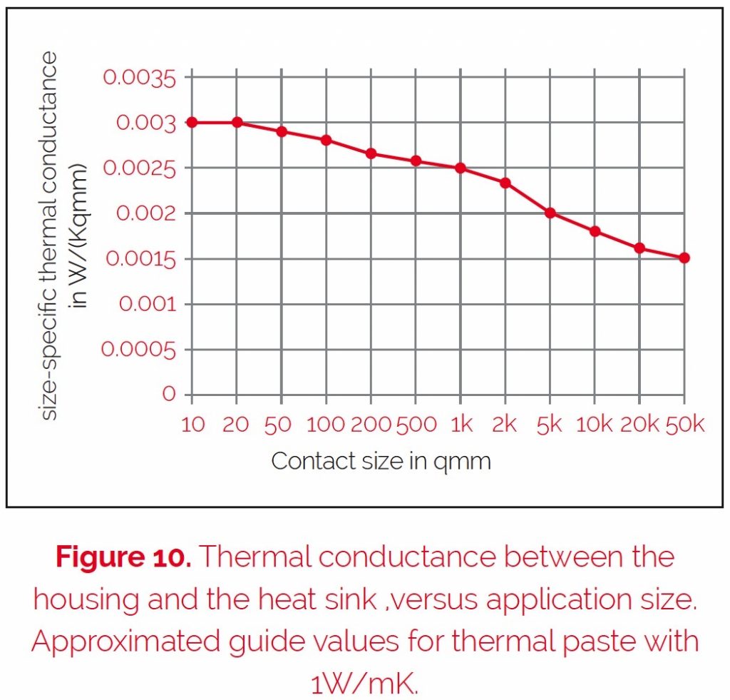
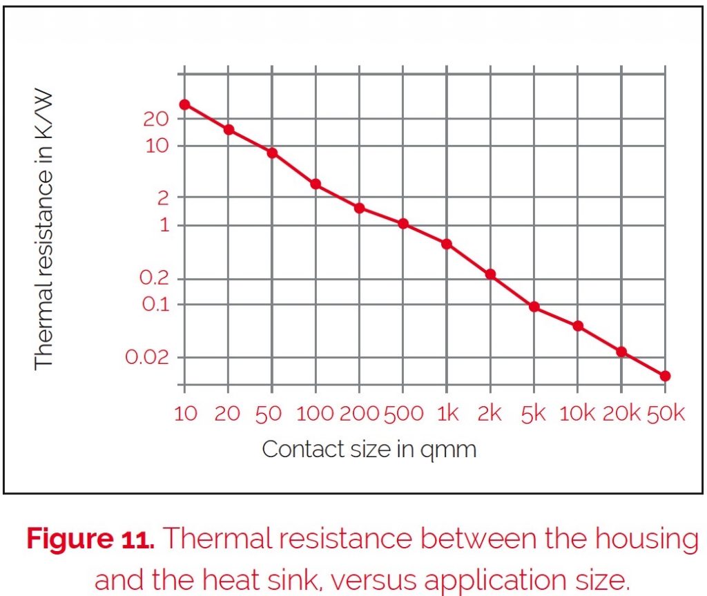
Figures 10 and 11 show the reachable average thermal conductance for an optimal application, and the absolute thermal resistance (RthRAppl) dependency
on the mounting point, with normal heat conduction paste. The decrease of the heat conductivity within big mounting areas results in the problem that it is virtually impossible to reach an optimal constant pressure to fix the elements on the heat sink.
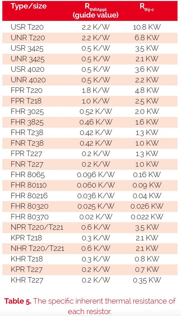
The results of these calculations are the thermal resistances between the mounting plate and the surface of the heat sink (RthRAppl) for the most important heat sink-mountable resistors within the Riedon product portfolio. The specific inherent thermal resistance of each resistor (resistance element / mounting plate) Rthj-c is shown in table 5.
![]()
With these specifications, it is possible to calculate the maximum allowed power dissipation. It is only necessary to define the temperature of the housing (ie, 85°C at the mounting plate). This temperature must be measured in the application.
An additional increase of heat dissipation can be reached with the use of a thermally-conductive grease. The disadvantage of using such an agent is that it is difficult to remove the resistor from the system, should it subsequently become necessary.