
Medical electronics equipment is no longer just found in hospitals, clinics and doctors’ surgeries. Neither is its use restricted to qualified practitioners. Instead designs have become smaller, more portable and easier to use to the point where now appliances like defibrillators are deployed in many public places such as sports venues, schools, airports, health and fitness clubs and many commercial and government offices.
Other devices such as blood glucose meters are today considered essential in the care of patients with diabetes and have evolved to be personal, pocket- sized units that can be carried everywhere. There is also equipment for patient monitoring, diagnostics and medication delivery that has been designed for in-home use, which often includes portable, body- worn elements.
Medical equipment generally demands the highest quality components to ensure safe and dependable operation; and portable equipment poses the additional challenges of compact size, the ruggedness needed to cope with harsh operating conditions, and usually needing to be battery- powered.
This chapter will explore two of these applications for portable medical electronics, looking at the specific requirements of the resistor technology used in their circuit designs.
Automatic External Defibrillators (AEDs)
Automatic external defibrillators operate on the same principle as the external defibrillators found in hospitals. They are used to treat victims of life-threatening cardiac arrhythmia (irregular heartbeat), which may lead to cardiac arrest, by administering an electrical shock to re-establish a normal heart rhythm. Note that external defibrillators are those where the charge is delivered via paddles placed on the chest whereas internal defibrillators, usually only found in operating theatres, use electrodes in direct contact with the heart.
The difference with hospital-type defibrillators is that they are designed for manual operation by trained doctors, paramedics and nursing staff who can diagnose the cardiac condition and will know what level of shock to apply. Also, while these defibrillators may have inbuilt electrocardiogram (ECG) readers, many hospital patients, especially those at risk of cardiac arrest, are likely to already be connected to comprehensive diagnostic monitoring equipment, which provides the clinician with all the information they require.
By contrast, AEDs are more portable devices, primarily intended for use by people who are not healthcare professionals, although ideally their operators will be first responders who have been trained in their use. Some ambulances may carry AEDs in addition to manual defibrillators. AEDs, as their name implies, automate the analysis and diagnosis of the patient’s heart rhythm and either administer a shock automatically or will clearly advise the user whether a shock is required and how to deliver it. Consequently AEDs are more limited in their capabilities and can only treat the common shockable types of arrhythmia (often referred to as VT and VF) and will not work with a ‘flatline’ condition after the heart has arrested.
AEDs are commonly considered as ‘public access’ devices, prominently located in shopping centers, railway stations and similar locations, but body-worn and other personal AEDs are becoming popular for vulnerable people and are even being promoted as essential home safety equipment.
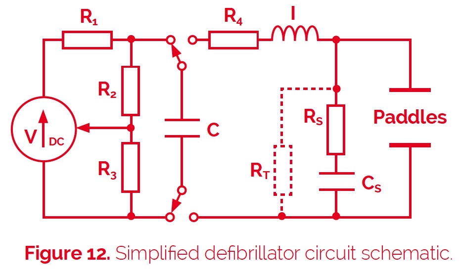
The basic electrical design of a defibrillator is relatively simple (shown in figure 12). The key element is the storage capacitor C, which is charged to a level sufficient to deliver a predetermined dose of electrical energy as a shock to the heart.
This schematic only shows the essential charge/ discharge circuitry and not the controls that drive the switches and automatically determine correct operation. The charging circuit comprises a DC supply and series resistor R1 , which limits the charging current and determines the charging time. Depending on the capacitor’s value and the required shock energy, the supply may well need to provide upward of 1000V, perhaps even as high as 5000V. So, in the case of a battery-powered portable AED, this will come from a DC-DC converter. The potential divider, formed by R2 and R3 , monitors the capacitor voltage and provides a lower voltage signal that is used to disconnect the supply once the required charge level is reached.
Discharge is via an inductor I, which in combination with resistor R4 produces a heavily damped pulse that typically delivers 100 joules of energy over a period of around 5ms. The system as shown provides a fixed polarity pulse whereas most defibrillator designs are now biphasic so as to reverse the polarity of alternate pulses. Biphasic defibrillators achieve higher success rates and operate at reduced energy levels. RS and CS form a snubber circuit while RT may be included to provide a means of testing the defibrillator output.
The performance requirements of the resistors used in AEDs, including the associated cardiac monitoring circuits, are quite demanding. Resistors R1, R2 and R4 in figure 11 must all be able to withstand high voltages but R1 is carrying the charging current so while its exact value (perhaps 100kΩ), and hence accuracy, is not so important, it will probably need to be capable of dissipating around 10W of power. R4 is used to shape the charge pulse delivered to the paddles so its value (e.g. 10Ω) and surge handling capacity (around 300 Joules) are key. The ratio of the values of R2 and R3 might be in the order of 500:1 to divide a supply voltage of say 1000V down to a level of 2V, compatible with the comparator input range of a typical microcontroller. Hence if R2 were 10MW then R3 would need to be around 20kW. Assuming the system can be calibrated, then again the exact values and tolerance of these devices are not important.
However, temperature stability and voltage linearity are critical performance characteristics, defined by the parameters of TCR (temperature coefficient of resistivity) and VCR (voltage coefficient of resistivity). Suitable values would be ±100ppm/°C for TCR and between -1 to -5ppm/V for VCR, which has a negative coefficient.
Riedon offers various types of resistors that address these requirements. For R1 its HTE thick-film range provides a non-inductive, axial-leaded design with a voltage rating up to 48kV, power ratings from 0.7 to 17Ω and resistances from 1kΩ to 100MΩ . With a ±100ppm/°C TCR specification the HTE series is also suitable for R2 and R3. For R4 and also to protect any sensitive monitor inputs that may be connected to the paddles, suitable pulse-withstanding resistors are required. For these Riedon recommends its UT series of wirewound resistors, which is capable of handling over 1000 Joules. A suitable value for RS would be 50W while RT might be around 5kW and again, the UT type provides the necessary pulse handling capability. R4, RS, and RT should all be non-inductive.
Blood Glucose Meters
Blood glucose monitoring enables diabetics to monitor their condition and respond to high or low blood sugar levels. Understanding how and why these levels change helps those affected manage their diet, exercise and medication regime. This is particularly important for sufferers of Type 1 diabetes (and some Type 2s) whose treatment requires insulin injections – regular blood glucose testing allows them to check the effectiveness of their last insulin dose and plan the next one.
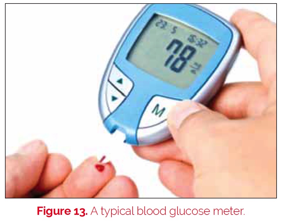
A blood glucose meter is an electronic device that provides a relatively simple means of measuring blood glucose levels. And advances in technology have provided pocket-size battery-powered units that are convenient to carry and easy to use so that testing can be carried out several times a day, helping patients maintain closer to normal blood glucose levels throughout the day.
Most blood glucose testing is performed by obtaining a small blood sample, typically by pricking a finger and applying the blood to a test strip that contains chemicals that react with the glucose.
Early measurements relied on a reaction that changed the color of the strip, which could either be crudely compared to a color reference chart or, more accurately, measured with a colorimeter.
The alternative measurement method uses an electrochemical reaction and it is the combination of this technology with an appropriate electrical metering circuit that forms the basis of most blood glucose meters today.
Such blood glucose meters, or ‘glucometers’ as they are frequently called, use test strips that absorb a defined amount of blood. The glucose in the blood is oxidized using an enzyme electrode as a catalyst; it is then re-oxidized with a mediator reagent, which in turn reacts with the electrode and generates an electrical current. The total charge (current times time) produced is then proportional to the amount of
glucose in the blood sample. This charge can either be measured over a period of time or, knowing the timing characteristic of the chemical reaction, the current can be measured after a predefined interval to provide an equivalent estimate of the glucose concentration.
The accuracy of glucometers is vitally important and is therefore defined by ISO standards. Accuracy is affected by many factors including the size and quality of the blood sample, ambient temperature and humidity, calibration and aging of the test strips, and ultimately the accuracy of the electrical measurement. The latter is something that is readily addressed by appropriate current measurement techniques using precision components.
Current sensing resistors provide the ideal solution. Like the shunt resistors used in traditional ammeters, the current is actually measured as a voltage drop across an accurately known, low-value resistor, placed in series with the load. In devices like glucometers that have digital displays, the voltage will be measured by an analog to digital converter (ADC), which will typically be an integrated function of the microcontroller used to process and output the glucose readings and provide overall control for the operation of the device.
Aside from their low resistance value, the key requirements for a current sensing resistor are accuracy and stability, across all operating conditions and over time. Riedon offers a number of different types of current sensing and shunt resistors for various applications. For this type of medical application, it particularly recommends either its CSR surface mount series or its through-hole mounting MSR series Riedon’s CSR series are ultra-low Ohm metal strip chip resistors with values from 0.5 to 15 mΩ, a tolerance of ±1%, and a TCR of ±50ppm/ oC. Three package sizes are offered, supporting power ratings from 1 to 3 Watts over a wide -55oC to +170oC operating temperature range. Its MSR resistors are available in values from 5 to 100 mΩ with a tolerance of ±1%, a TCR of ±20ppm/°C, and power ratings of 1, 3 or 5W. Their bare metal element design and welded construction provide a low inductance solution that is also very economical.
Current sensing, using the same principles as above, is also very important in portable medical devices for monitoring battery life. Resistors of the type described above, or perhaps similar specifications but higher power resistors from Riedon, will provide the right solution for this task.