
The subject of power supplies is potentially very broad and the application of resistors in power supplies is quite diverse. Here we will focus on power supply units (PSUs) designed for use in electronic appliances that nominally require fixed DC outputs ranging from just a few volts up to a few kV.
Whether such end equipment is destined for consumer, commercial or industrial markets, the PSU designer will need to pay heed to stringent safety, environmental and other regulations in addition to meeting the basic electrical performance requirements. As well as considering the role of resistors in regulating a power supply’s output voltage (or current), we will examine how resistors protect a supply from potential fault conditions, such as output overload, output short- or open-circuit, and input surge currents, which can result in a fire or present a shock hazard to users.
Power supplies are often defined by their input source, AC or DC, and whether they use linear or switched mode regulation to achieve the desired DC output. AC-DC supplies are typically line powered but a DC in, DC out supply could just be a linear circuit that regulates the output from a battery or other DC source to produce a lower DC level. The term DC-DC converter is usually reserved for supplies that use switched-mode techniques, which can support both step-down (buck) and step-up (boost) conversion for lower and higher voltages respectively.
While most power supply manufacturers offer a range of standard units to satisfy various end- equipment requirements, some applications demand a custom solution. As a manufacturer and supplier of high-performance resistors, Riedon has the experience to help designers choose the right component.
Back to Basics – Simple Linear Regulators
Understanding some of the basics of power supply design would seem a good way to appreciate the importance of seemingly mundane components like resistors. From their college days, most engineers will remember designing Zener regulators to provide a constant voltage to a permanently connected load, represented by R2 in figure 16. The principle is
straightforward and simply requires the value of R1 to be calculated to provide both the minimum current needed to ensure the Zener diode operates in its constant voltage breakdown region, as well as the full load current.
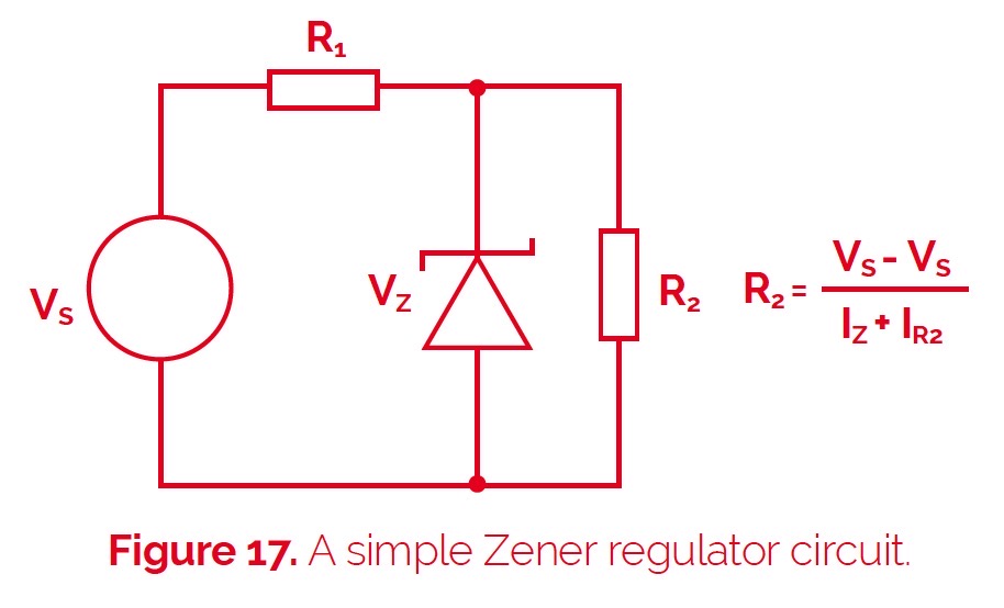
Zener regulators are generally fine for low power applications where both the supply voltage and load are reasonably constant. However, in a shunt configuration like this, a significant reduction in load current or increase in supply voltage may result in an increased current through the Zener diode that exceeds its maximum power dissipation. From the resistor perspective though, other than the power rating needed to handle the combined load and Zener currents, the performance requirements on R1 are minimal.
Greater sophistication in linear regulation is achieved with a series design that uses a pass transistor to regulate the load current and drop the input voltage to the required output level. This concept is shown in figure 18 and such designs are typical of integrated circuit (IC) regulators and also low drop-out (LDO) regulators, which often provide a regulated supply at the “point of load”.
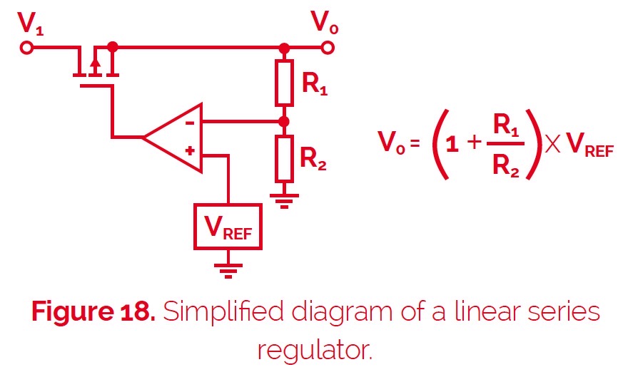
The potential divider formed by resistors R1 and R2 is used to sense and set the output voltage relative to an accurate reference voltage. In the case of fixed output linear regulator ICs this divider will be internal but, for other regulators, ICs, and PSUs, having one or both arms of the voltage divider external to the device provides the necessary flexibility to adjust the output voltage as required.
The choice of resistor values for the divider chain is primarily determined by their ratio, so a key consideration is their impact on total power supply accuracy. Provided that the comparator circuit has a high gain and high input impedance, the effects of resistor tolerance can be calculated by modeling their worst case value in the output voltage equation above, e.g. calculating first with R1 at its maximum value and R2 at its minimum and then vice versa to find the potential deviation in output voltage.
To illustrate this: If VREF is 1.2V and R2 is nominally 5kW then for a 3.3V output, R1 needs to be 8.75kW. So if R1 and R2 are 1% tolerance devices the worse case output error is ±1.27%. However, the output error is reduced for an output voltage closer to the voltage reference e.g. for a 1.8V output R1 needs to be 2.5kW and the output error is ±0.67%. These errors due to resistor tolerance add to the rated accuracy of the device itself, so if the device is nominally specified to ±1% then it is usually desirable that the error due to resistor tolerance is not significantly greater.
Switching Technology Improves PSU Efficiency
Because linear power supplies divide the DC source to provide a regulated output voltage, energy is being consumed in the series pass device as well as the load. This results in low efficiency, especially if the voltage dropped by the regulator is significant.
A switched-mode power supply (SMPS) takes an unregulated DC source, which may be from an AC line input that has been directly rectified and smoothed, and switches it on and off at high frequency (typically 10kHz – 1MHz) with a duty cycle that determines the resulting DC output voltage, once that high-frequency AC signal has been rectified and smoothed. Output regulation of an SMPS uses a similar output sensing arrangement to the linear series regulator described earlier but now the feedback signal from the potential divider is used to control the switching frequency and duty cycle.
By avoiding the voltage dropped by a linear regulator that continually dissipates power, a switched-mode supply, where the pass transistor is either fully on or fully off, achieves much higher efficiency, which in good designs can be up to 95%. What’s more, compared to a linear AC-DC supply of similar rating, switched-mode supplies will be much smaller because the high-frequency transformer (typically required to provide electrical isolation from the line input) and associated filter/reservoir capacitors are physically smaller than the equivalent components in a linear supply.
However, one issue with switched-mode supplies is that they require a minimum load to operate correctly and can be damaged under no-load conditions. For this reason, it is not uncommon to build in a dummy load in the form of a suitable power resistor that will draw the minimum specified load current in the event that the primary load becomes disconnected. Of course, such a load resistor will itself consume power, which not only needs to be taken into account in the resistor specification but also reduces the efficiency of the supply. An alternative solution is to employ a shunt resistor that can be connected across the output to divert current should the power supply detect that the intended load has gone open circuit. Switched-mode supplies usually include other safety features such as current limiting to protect against output short-circuit and shut down the supply. Low ohmic value, high-power shunt resistors can also be used in a similar crowbar fashion to protect users from over-voltage conditions.
DC-DC converters also use switching technology to convert from one DC voltage to another. Indeed the step-down form of DC-DC converter (often referred to as a “buck” converter) essentially operates in the same way as a SMPS. Step-up, or “boost”, DC-DC converters use charge pump techniques to raise the input voltage to a higher output level. In general, though, the same methods of regulating the output voltage still apply along with similar techniques for protecting against fault conditions.
Further roles for resistors in power supplies
In addition to their use for voltage sensing/setting and as dummy loads or shunts, resistors can play a number of other important roles in power supply designs:
- Bleed resistors placed in parallel with a power supply’s load are used to discharge the smoothing capacitors used in linear AC-DC converters and also the reservoir capacitors employed by DC-DC These capacitors can retain charge long after a supply is turned off, presenting a potentially lethal shock hazard to users accessing the supply. Clearly the bleed resistor’s value should be calculated to be high enough not to consume significant power when the supply is operating normally but low enough to discharge the unit relatively quickly when the supply is switched off.
- Inrush limiting resistors of a few Ohms or less in series with the AC line can address the problem with AC-DC converters where a large surge current may occur at switch-on as the bulk storage capacitor is initially charged. The alternative, particularly for higher-wattage supplies, is to use negative temperature coefficient (NTC) resistors, which initially present a higher resistance that falls as their temperature increases through self-heating. But, to ensure an acceptably low resistance value during normal operation, NTC resistors have to continue operating at this temperature, which may be incompatible with other constraints on the power supply’s operation. The use of specialized pulse withstanding resistors may be a better solution – these are rated according to their energy-handling capacity in Joules rather than the continuous power rating (in Watts), which the high inrush current level would otherwise dictate.
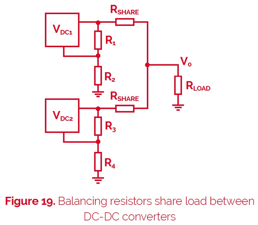
- Balancing resistors provide a way for sharing a load either between two or more DC-DC converters. Operating DC-DC converters in parallel may be more cost-effective than using a single higher-current unit or maybe more desirable in some instances because of physical size constraints or thermal considerations. However, simply tying the outputs of two converters together does not ensure they share the load current equally. The equal value R SHARE resistors shown in figure 19 accommodate the difference between the regulated outputs of each converter.
A similar situation applies to the power transistors used to regulate the load in various power supply designs. Rather than using a single device rated at the full load it may be better to use several transistors in parallel to share the load. So, as with the paralleled DC-DC converter, load-sharing resistors can be placed in series with the output of each transistor to equalize the current.
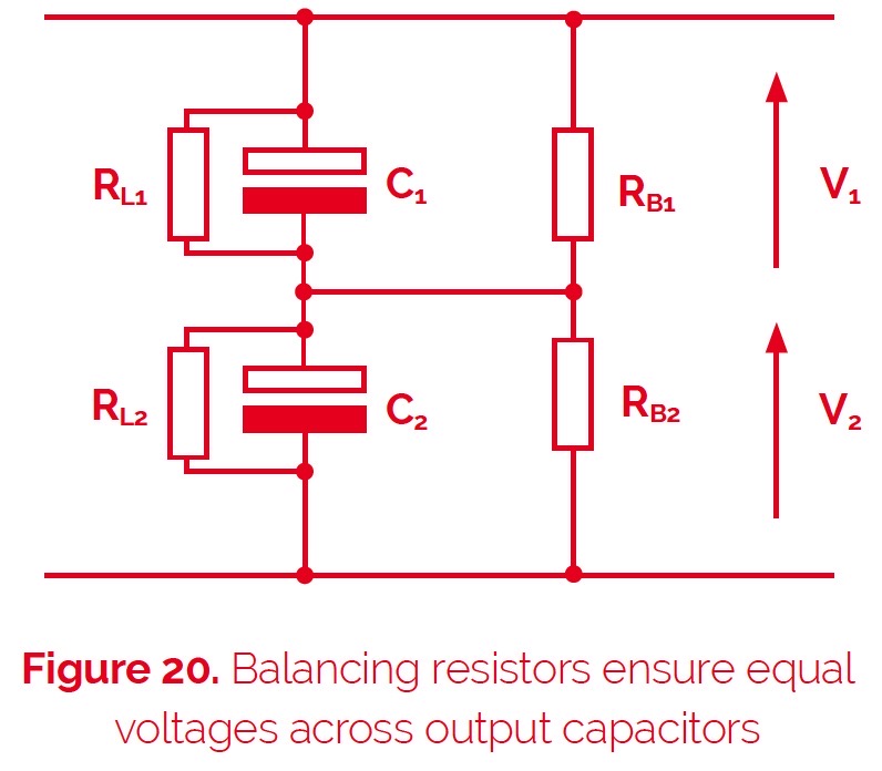
A third balancing scenario is encountered where reservoir capacitors are connected in series to the outputs of high voltage DC supplies, as shown by C1 and C2 in figure 20. The problem here is that electrolytic capacitors have leakage currents that can be considered as resistors in parallel with the capacitor. Unfortunately, these leakage resistances (RL1 and RL2 ) can differ significantly in value, even for the same value capacitors, but they act as a potential divider across the output resulting in unequal voltages across the capacitors, which could exceed their maximum rating. A solution is to add more accurately matched, lower-value external resistors (RB1 and RB2 ) across the capacitors to counteract the leakage effect.
- High voltage dividers are used to scale down the output of a high voltage power supply to provide feedback for regulation purposes and potentiometric ratios as high as 1000:1 are not uncommon. Voltage divider resistors are also used in applications such as automatic defibrillators to monitor the high voltage supply used to charge the storage capacitor and switch the supply off once the required charge level is reached. High-performance resistors for custom power supplies.
- High current sensing is where a low ohmic precision resistor is used in series with the supply current to measure current by measuring the voltage it drops, using the principle of a shunt ammeter. The dilemma facing the designer is the conflict between minimizing heat generation and power loss (P=I 2R) by choosing a low resistance, versus a higher resistance that results in a larger voltage drop, which is easier to measure.
The use of resistors in power supplies presents a multitude of differing performance requirements. These include the need for precise values with low tolerances, devices that can handle high current, high voltage, or high power, as well as more specialized components offering low ohmic values, superior temperature stability, or the ability to withstand surge currents. Riedon, as a specialist manufacturer and supplier of high-performance resistors, has solutions for all these requirements. Examples include its Power Film (PF Series) resistors, which provide resistances from 20mΩ to 100kΩ with tolerances from 0.1% and power handling from tens to hundreds of Watts, and its UAL resistors that employ an aluminum housing for high power dissipation but also provide excellent pulse handling, low ohmic values (from 5mΩ), tolerances from 0.01% and a low TCR (temperature coefficient of resistance) of ±20ppm/K.