
Here’s a brief glossary of the most important terms used when describing resistors’ characteristics.
Tolerance
Resistor tolerance is the deviation from the nominal value. It is expressed as a ±%, measured at 25°C with no load applied. Some resistor designs have extremely tight tolerances. For example, precision wirewound resistors are made with tolerances as tight as ±0.005%. Film resistors typically have tolerances of ±1% to ±5%. In applications like precision voltage dividers and networks, the designer should consider resistor sets matched for resistance or ratio tolerances. Often, these matched sets save cost over buying individual resistors with very tight resistance tolerances.
Accuracy
Resistor accuracy is not the same as tolerance. Accuracy is the resolution (or number of digits) from the mantissa of the nominal resistor value. For example, 5.045Kohm would be 4 digits accuracy.
Stability
Stability is defined as the repeatability of resistance of a resistor over time when measured at a referenced temperature and subjected to a variety of operating and environmental conditions. It’s normally expressed in percent from the absolute resistor value (the reference value) at t=0.
Stability is difficult to specify and measure since it is application-dependent. Experience with practical circuits has given us some guidelines: bulk metal and wirewound designs are typically most stable, while designs using composition materials are less stable. For the highest resistance stability, it is best to operate critical resistors well within their power limits, with limited temperature rise.
Reliability
Reliability is the statistical probability that a resistor will perform its function. Normally, it is specified as failure rate per 1,000 hours of operation. Various statistical studies are used at arriving at these failure rates by testing large samples. Reliability is seldom defined for commercial products but is a common requirement for critical designs such as in aerospace and medical applications.
Frequency Response and Rise Time
Frequency response relates to the resistor’s change in impedance with frequency, caused by reactive components from its inductance and capacitance. Rise time is an associated parameter, relating the resistor’s response to a step or pulse input.
Some wirewound designs use special winding techniques to minimize reactive components. Typical reactive values for these special designs are less than 1μh inductance for a 500Ω resistor, and less than 0.8pf capacitance for a 1MΩ resistor. A typical fast rise time resistor has a rise time of 20nsec or less.
Voltage Coefficient
Voltage coefficient is the change in resistance with applied voltage. It is a function of the resistor’s value and its composition.
Noise
Noise does not affect the resistor’s value but can generate circuit errors in high gain and sensitive circuits. Wirewound and metal film resistors have the best noise performance: carbon composition and thick film have higher noise characteristics.
Thermocouple Effect
The thermocouple effect generates a thermal electro-motive force (EMF) at the junction of two dissimilar metals. In resistors, it is caused by the materials used in leads and the resistive element. It is normally insignificant but may be important in high gain or critically balanced circuits and low ohm resistors. Thermal EMF is minimized by keeping the resistor leads and body at the same temperature.
Temperature Rating
Temperature rating is usually the maximum operating temperature of the resistor. An operating temperature range is often specified: for example, -55°C to +275°C.
Thermal Resistance
Thermal resistance is the factor of proportionality between power dissipation and over-temperature and is usually expressed as
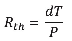
where Rth is the thermal resistance, dT is the temperature change and P is the power dissipated.
Temperature Coefficient of Resistance
The absolute ohmic value of a resistor depends on temperature. A resistor’s Temperature Coefficient of Resistance (TCR) tells how much its resistance value changes as its temperature changes and is expressed in parts per million per degree Centigrade (ppm/°C). A wide range of TCRs are available to the designer (typically from ±1 ppm/°C to ±6700 ppm/°C) for specific applications.
Specifying TCR is important in applications where the change in resistance with temperature changes must be small. Equally important may be applications where a specific TCR is required (temperature compensation circuits and temperature-sensing applications for example). Typically, there are two contributors to temperature-related resistance changes; the resistor’s temperature increases as it dissipates power, and ambient temperature changes.
Often matching TCRs for pairs or sets of resistors is more important than the actual TCR itself. In these cases, matched sets are available which assure that resistance values of the set track in the same magnitude and direction as operating temperature changes. In this case, the TCR matching is the maximum allowed TC difference of different resistors in the network.
Special wire alloys are formulated to have special temperature coefficients. For example, “Evenohm” (a trade name for a low TCR wire alloy) is formulated to have a small TCR of 5 to 20ppm/°C. Pure nickel has a much larger TCR of 6700ppm/°C. Copper has a TCR of 3900ppm/°C. These, and other alloys allow tailoring of the resistor to desired characteristics in applications where temperatures change.
As a practical example, a resistor with a resistance of 1000 ohms, made from pure nickel wire, would have a new resistance of 1670 ohms if we increase its temperature from 20°C to 120°C. In the same application, a resistor made with Evenohm wire would increase to only 1001 ohms.
Power Rating
When applying an electric voltage in a resistor, the energy is converted into heat. The result of the energy per unit time is the power dissipation. Depending on the heat removal, there is a temperature rise of the resistance element under steady-state conditions.
Power ratings are normally specified at +25°C and must be reduced as the resistor’s temperature increases. A derating chart is often used to specify the rated power vs. ambient temperature. Since these parameters are application-dependent, power derating curves or charts should be considered general rather than absolute. Power ratings are based on many factors. The most stable designs use the largest physical size operating at conservative temperatures and power ratings.
Nominal power dissipation
The maximum permanent allowed power dissipation without exceeding the limiting temperature of the resistor. The nominal power dissipation in Riedon specifications is measured under the following conditions: free standing assembly, ambient temperature of 70°C without additional cooling, or assembled on a heat sink with optimal fixed mounting.
U-Characteristic for Wirewound Resistors
Standard silicone-coated, wirewound resistors (such as the Riedon UT-series) are rated under two load/ power characteristics to allow more flexibility to meet the user’s application requirements.
The standard maximum power ratings are called U-characteristic ratings and define the maximum power to be applied to the resistor to ensure that the tolerance of the part would be maintained under normal usage for a period of one year. Drift in a wirewound resistor is a function of temperature and operating a resistor within this U-characteristic power level limits the maximum operating temperature of the resistor (250°C) within a range that ensures the tolerance specification is correct.
V-Characteristic for Wirewound Resistors
A second, higher power rating is also assigned to a resistor which allows the same resistor (same physical size) to be operated at a higher power level and higher temperature range (up to 350°C), but which also requires that the environmental performance tolerances of the part be increased to reflect the higher operating temperatures. This V-characteristic power level is little-used, but if a customer requires higher power capability in the same size package and is willing to accept degraded environmental performance specifications, the V-characteristic part offers a solution.
Some Other Typically Specified Parameters
- Impulse strength is the maximum allowed short-duration (impulse) electric energy that the resistor can withstand without exceeding the limiting temperature.
- Limiting voltage, also referred to as dielectric strength, is the maximum allowable voltage that can be applied to the
- Limiting current is the maximum allowable current through the
- Insulation strength, also known as breakdown rating, is the maximum allowable voltage between the resistance element and the environment (chassis or heat sink).
- Standard conditions are the measurement conditions for defining the resistor value, tolerance and stability. In Riedon laboratory and production processes, the reference temperature is 25degC +/- 2degC.
Aryton-Perry Windings
In Aryton-Perry windings, a layer is first wound in one direction. After a layer of insulation, the next winding is wound in the opposite direction with the turns crossing every 180 degrees. This configuration minimizes the inductance of the resistor.
Low Value Resistors for Shunt and Current Sensing
Special low ohm power resistors are often used for measurement shunts, and for current sensing applications. The value of these resistors is low, generally less than 0.1 ohm. Some special considerations apply.
Lead material should be of good conductivity to prevent the lead resistance from becoming a significant portion of the total resistance. Measurement points should be specified for critical applications; a point 3/8” from the end of the resistor body is universally accepted.
Four-Terminal (Kelvin) Connections
Four terminal leads are often specified for low ohm current sensing applications where lead resistance is a significant factor in total resistance. The Kelvin connection eliminates the error voltage due to IR-drop that would be present in the leads of a two-terminal resistor.